Computer Network CS 144- bi-directional byte stream(双向字节流)
- TCP (传输控制协议)
- http (超文本传输协议)
- Network Address translation(网络地址转换)
- rendezvous rely servers(集合中继服务器)
1-1 Network Application
HTTP(超文本传输协议
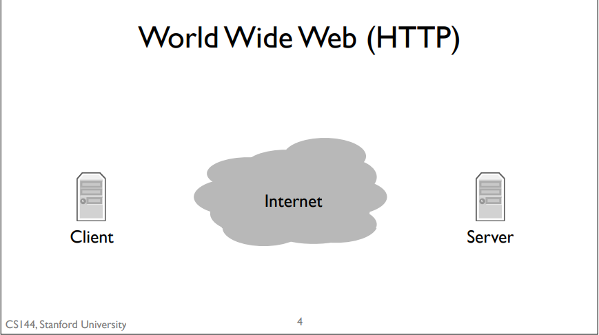
basic model: client sends a request by writing to the connection, the server reads the request, processes it, and writes a response to the connection, which the client then reads.
Bit Torrent
What is bit torrent?
Bit Torrent is a program that allows people to share and exchange large files. In Bit Torrent a client requests documents from other clients. Bit Torrent breaks files up into chunks of data called pieces. When a client downloads a complete piece from another client, it then tells other clients it has that piece so they can download it too. These collections of collaborating clients are called swarms.
simple model:. When a client wants to download a file, it first has to find something called a torrent file. Usually, you find this using the world wide web and download it using, you guessed it, HTTP. This torrent file describes some information about the data file you want to download. It also tells Bit Torrent about who the tracker is for that torrent. A tracker is a node that keeps track (hence the name) of what clients are members of the swarm. To join a torrent, your client contacts the tracker, again, over HTTP, to request a list of other clients. Your client opens connections to some of these clients and starts requesting pieces of the file. Those clients, in turn, can request pieces. Furthermore, when a new client joins the swarm, it might tell this new client to connect to your client. So rather than a single connection between a client and one server, you have a dense graph of connections between clients, dynamically exchanging data.
Skype
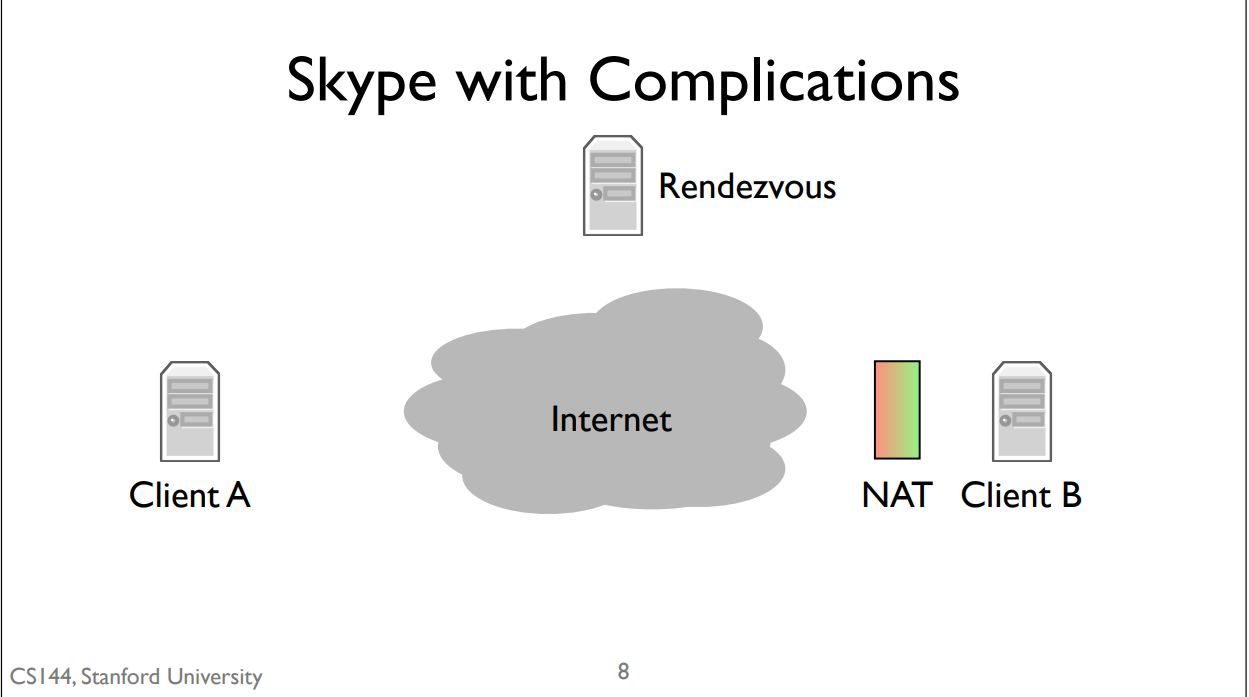
NAT: if you’re behind a NAT then you can open connections out to the Internet, but other nodes on the Internet can’t easily open connections to you.
simple mode:It does so using something called a rendezvous server. When you log into Skype, your client opens connections to a network of control servers. In this case, client B opens a connection to the rendezvous server. This works fine because the server isn’t behind a NAT and client B can open connections out without any problems. When client A calls client B, it sends a message to the rendezvous server. Since the server has an open connection to client B, it tells B that there’s a call request from A. The call dialog pops up on client B. If client B accepts the call, then it opens a connection to client A. Client A was trying to open a connection to client B, but since B was behind a NAT, it couldn’t. So instead it sends a message to a computer that client B is already connected to, which then asks client B to open a connection back to client A. Since client A isn’t behind a NAT, this connection can open normally. This is called a reverse connection because it reverses the expected direction for initiating the connection. Client A is trying to connect to client B, but instead client B opens a connection to client A.
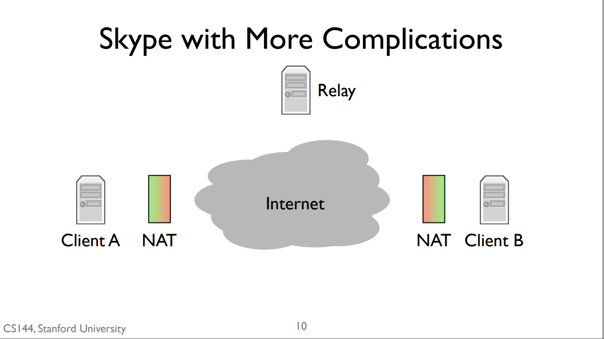
simple model: Skype introduces a second kind of server, called a relay. Relays can’t be behind NATs. If both client A and client B are behind NATs, then the communicate through a relay. They both open connections to the relay. When client A sends data, the relay forwards it to client B through the connection that B opened. Similarly, when client B sends data, the relay forwards it to client A through the connection client A opened.
1-2 Layer Internet Model
Link Layer
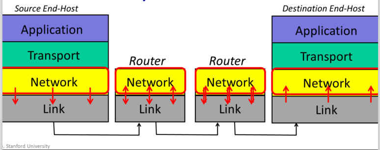
The Internet is made up of en1d hosts, links and routers. Data is delivered hop-by-hop over each link in turn. Data is delivered in packets. A packet consists of the data we want to be delivered, along with a header that tells the network where the packet is to be delivered, where it came from and so on.
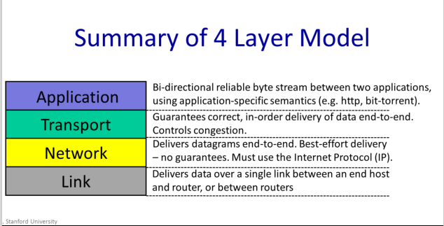
Link Layer: The Link Layer’s job is to carry the data over one link at a time.__
Example: Ethernet,WiFi and 5G
Network Layer
packets:
| data | header contains “to” and from “address” |
|---|
Network Layer:The network layer’s job is to deliver packets end-to-end across the Internet from the source to the destination.
The Network hands the datagram to the Link Layer below, telling it to send the datagram over the first link. In other words, the Link Layer is providing a service to the Network Layer. Essentially, the Link Layer says: “if you give me a datagram to send, I will transmit it over one link for you.
At the other end of the link is a router. The Link Layer of the router accepts the datagram from the link, and hands it up to the Network Layer in the router. The Network Layer on the router examines the destination address of the datagram, and is responsible for routing the datagram one hop at a time towards its eventual destination. It does this by sending to the Link Layer again, to carry it over the next link. And so on until it reaches the Network Layer at the destination.
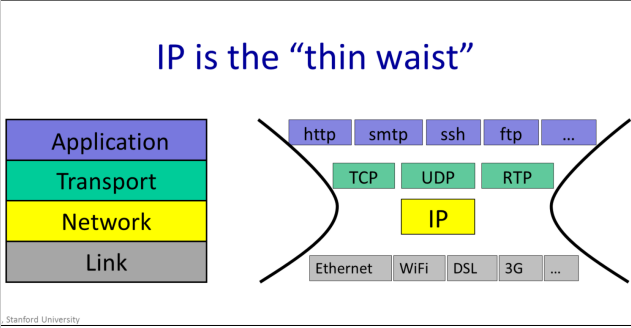
We Must Use Internet Protocal(IP)
In the internet, the network layer is special: When we send packets into the Internet, we must use the Internet Protocol. It is the Internet Protocol, or IP, that holds the Internet together
IP makes a best-effort attempt to deliver our datagrams to the other end. But it makes no promises
IP datagrams can get lost, can be delivered out of order, and can be corrupted. There are no guarantees.
Transport
The most common Transport Layer is TCP. TCP makes sure that data sent by an application at one end of the Internet is correctly delivered – in the right order to the application at the other end of the Internet. If the Network Layers drops some datagrams, TCP will retransmit them, multiple times if need-be.
Example: TCP UDP
Application
There are of course many thousands f applications that use the Internet. While each application is different, it can reuse the Transport Layer by using the well-defined API from the Application Layer to the TCP or UDP service beneath.
How it works
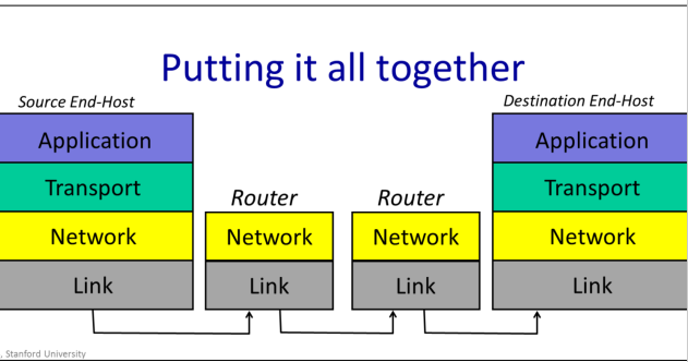
When a web client requests a page from a web server, the web client sends a GET request. This is one of the commands of the hypertext transfer protocol, or http. http dictates that the GET command is sent as an ASCII string, along with the URL of the page being requested. As far as the Application Layer is concerned, the GET request is sent directly to its peer at the other end – the web server Application . The Application doesn’t need to know how it got there, or how many times it needed to be retransmitted. At the web client, the Application Layer hands the GET request to the TCP layer, which provides the service of making sure it is reliably delivered. It does this using the services of the Network layer which has the job of breaking the data into packets, each with the correct destination address and in turn uses the services of the Link Layer.
summary
7-layer OSI Model
1-3 IP service
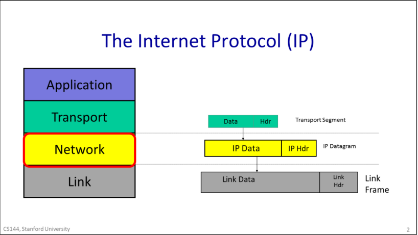
IP datagrams consist of a header and some data. When the transport layer has data to send, it hands a Transport Segment to the Network layer below. The network layer puts the transport segement inside a new IP datagram. IP’s job is to deliver the datagram to the other end. But first, the IP datagram has to make it over the first link to the first router. IP sends the datagram to the Link Layer that puts it inside a Link frame, such as an Ethernet packet and ships it off to the first router.
IP Property
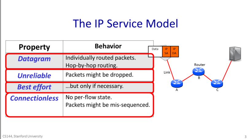
The IP service can be characterized by four properties listed here. It sends Datagrams from end host to end host; it is unreliable, but makes a best-effort to deliver the datagrams. The network maintains no per-flow state associated with the datagrams.
properties
- The IP service model provides a service which includes the routing to the destination.
- IP is unreliable. IP makes no promise that packets will be delivered to the destination. They could be delivered late, out of sequence, or never delivered at all. It’s possible that a packet will be duplicated along the way, for example by a misbehaving router. The key thing to remember is that IP is unreliable and makes no guarantees.
- It won’t drop datagrams arbitrarily just because it feels like it.
- IP is an extremely simple, minimal service. It maintains no state at all related to a communication. We say that a communication service is “connectionless” because it doesn’t start by establishing some end to state associated with the communication. In other words, when we make a Skype call lasting several minutes and consisting of many IP datagrams, the IP layer maintains no knowledge of the call, and simply routes each datagram individually and independently of all the others.
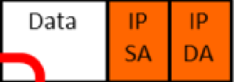
The header contains the IP address of the destination, which we abbreviate here as “IP DA” for IP destination address. The forwarding decision at each router is based on the IP DA. The datagram header also contains an IP source address, or “IP SA”, saying where the packet came from, so the receiver knows where to send any response.
forwarding table
each router contains a forwarding table that tells it where to send packets matching a given destination address. The router doesn’t know the whole path – it simply uses the destination address to index into its forwarding table so that it can forward the packet to the next hop along the path towards its final destination. Hop by hop, step by step the packet makes its way from the source to the destination using only the destination address in the datagram.
Reasons Why IP is simple
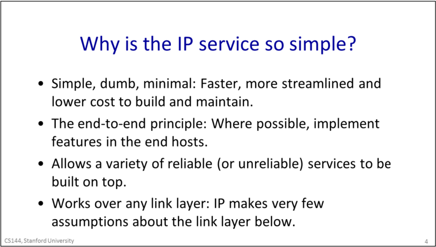
- To keep the network simple, dumb and minimal. Faster, more streamlined and lower cost to build and maintain. It was believed that if the network is kept simple with very features and requirements, then packets could be delivered very quickly, and at low cost. The thinking was that a simple network could be made to run very fast using dedicated hardware. And given that the network is implemented by a large number of routers scattered throughout the network, if they could be kept simple then are likely to be more reliable, more affordable to maintain and will need to be upgraded less often.
- The end to end principle: Where possible, implement features in the end hosts.The basic idea is to place as much intelligence as possible at the end points.This can have several advantages, such as making sure the feature is implemented correctly for the application, and it is easier to evolve and improve a feature if it is implemented in software on end computers rather than baked into the hardware of the Internet.
- Allows a variety of reliable (or unreliable) services to be built on top. If IP was reliable – in other words if any missing packets were retransmitted automatically – then it would not be ideal for some services. For example, in real time applications like a video chat, there might be no point in retransmitting lost data, because it might arrive too late to be useful. Instead, the application might choose to show a few blank pixels or use the pixels from the frame before. By not providing any reliability guarantees, IP lets the application choose the reliability service its needs.
- Works over any link layer: IP makes very few assumptions about the link layer. IP makes very little expectation of the Link layer below – the link could be wired r wireless, and requires no retransmission or control of congestion.
other IP service
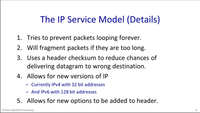
- IP tries to prevent packets from looping forever. This is most likely to happen when the forwarding tables are changing and they temporarily get into an inconsistent state. Rather than try to prevent loops from ever happening – which would take a lot of complexity - IP uses a very simple mechanism to catch and then delete packets that appear to be stuck in a loop. To do this, IP simply adds a hop-count field in the header of every datagram. It is called the time to live, or TTL field. It starts out at a number like 128 and then is decremented by every router it passes through. If it reaches zero, IP concludes that it must be stuck in a loop and the router drops the datagram.
- IP will fragment packets if they are too long. IP provides some header fields that we will see in a minute to help the router fragment the datagram into two self-contained IP datagrams, while providing the information the end host needs to correctly reassemble the data again.
- IP uses a header checksum to reduce chances of delivering a datagram to the wrong destination.IP includes a checksum field in the datagram header to try and make sure datagrams are delivered to the right location.
- Allows for new versions of IP. There are two versions of IP in use today: IPv4, which is used today by over 90% of end hosts. It uses the 32bit addresses you are probably familiar with. Because we are running out of IPv4 addresses, the Internet is in a gradual transition to IPv6, which uses 128 bit addresses instead.
- IP allows new fields to be added to the datagram header. This is a mixed blessing. On the one hand, it allows new features to be added to the header that turn out to be important, but weren’t in the original standard. On the other hand, these fields need processing and so require extra features in the routers along the path, breaking the goal of a simple, dumb, minimal forwarding path. In practice, very few options are used or processed by the routers.
IPV4 Datagram
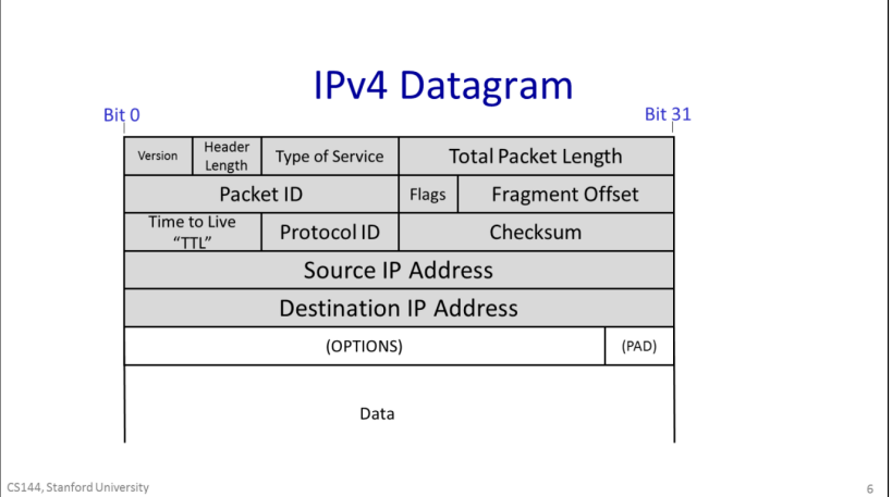
- The Protocol ID, that tells us what is inside the data field. Essentially, it allows the destination end host to demultiplex arriving packets, sending them to the correct code to process the packet. If the Protocol ID has the value “6” then it tells us the data contains a TCP Segment, and so we can safely pass the datagram to the TCP code and it will be able to parse the segment correctly. The Internet Assigned Numbers Authority (IANA) defines over 140 different values of Protocol ID, representing different transport protocols.
- The Version tells us which version of IP – currently, the legal values are IPv4 and IPv6.
- The Total packet length can be up 64kBytes including the header and all the data.
- The Time to Live field helps us to prevent packets accidentally looping in the network forever.
- Sometimes a packet is too long for the link it is bout to be sent on. The Packet ID, Flags and Fragment Offset all help routers to fragment IP packets into smaller self-contained packets if need-be.
- The Type of Service field gives a hint to routers about how important this packet is.
- The Header Length tells us how big the header is — some headers have optional extra fields to carry extra information.
- a checksum is calculated over the whole header so just in case the header is corrupted, we are not likely to deliver a packet to the wrong desination by mistake.
1-4Life of Packet
three way handshack
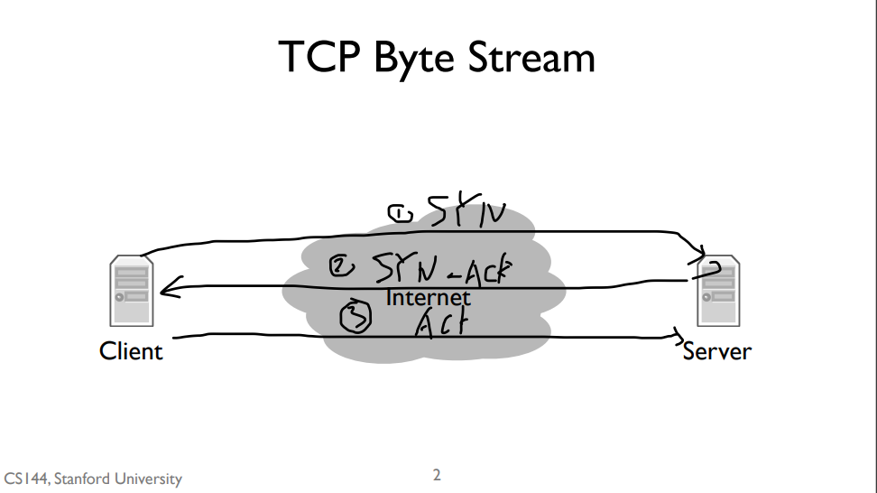
The first step of handshake is when the client sends a “synchronize” message to the server, often called a SYN. The second step is when the server responds with a “synchronize” message that also acknowledges the clients “synchronize”, or a “synchronize and acknowledge message”, often called a SYN-ACK. The third and final step is when the client responds by acknowledging the server’s synchronize, often called an ACK. So often the three way handshake is described as “synchronize, synchronize and acknowledge, acknowledge”, or “SYN, SYN-ACK, ACK”.
TCP port
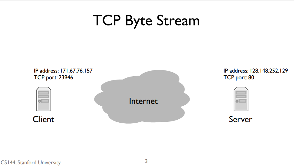
Recall that the network layer is responsible for delivering packets to computers, but the transport layer is responsible for delivering data to applications. From the perspective of the network layer, packets sent to different applications on the same computer look the same. This means that to open a TCP stream to another program, we need two addresses. The first, an Internet Protocol address,is the address the network layer uses to deliver packets to the computer. The second, the TCP port, tells the computer’s software which application to deliver data to. Web servers usually run on TCP port 80. So when we open a connection to a web server, we send IP packets to the computer running the web server whose destination address is that computer’s IP address. Those IP packets have TCP segments whose destination port is 80.
router
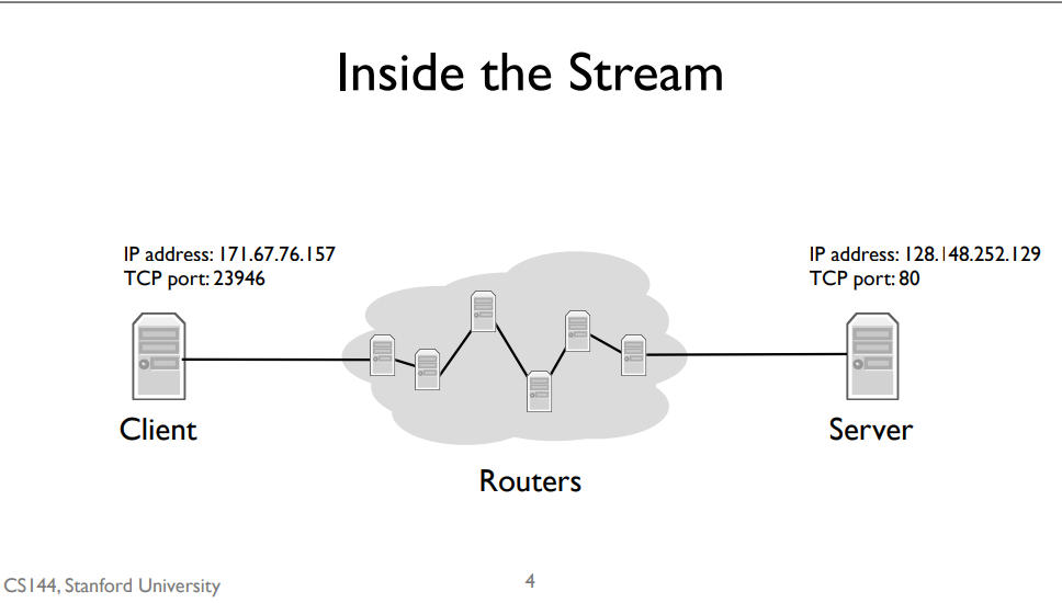
But how do those IP packets get to their destination? We don’t have a direct wire connecting my client to the server. Instead, my client is connected to an intermediate computer, a router. This router is itself connected to other routers. IP packets between the client and server take many “hops,” where a hop is a link connecting two routers. For example, since my client is on a WiFi network, the first hop is wireless to the WiFi access point. The access point has a wired connection to the broader Internet, so it forwards my client’s packets along this wired hop. A router can have many links connecting it. As each packet arrives, a router decides which of its links to send it out on. Routers have IP addresses, so it’s also the case that it might not forward a packet but rather deliver it to its own software. For example, when you log into a router using TCP, the IP packets are destined to the router’s own IP address
forwarding table
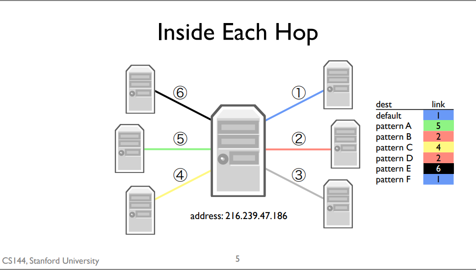
A forwarding table consists of a set of IP address patterns and the link to send across for each pattern
When a packet arrives, the router checks which forwarding table entry’s pattern best matches the packet. It forwards the packet along that entry’s link. Generally, “best” means the most specific match. The default route is the least specific route. It matches every IP address. If,when a packet arrives, there isn’t a more specific route than the default route, the router will just use the default one.
1-5 packect switching
packet switching
Independently for each arriving packet, pick its outgoing link. If the link is free,send it. Else hold the packet for latter.
Packet switching is the idea that we break our data up into discrete, self-contained chunks of data. Each chunk, called a packet, carries sufficient information that a network can deliver the packet to its destination. So let’s say we have a source and a destination, and a network of packet switches A, B, and C between them. When A receives a packet for the destination, it sends it along the link to B. When B receives a packet for the destination, it sends it along to C. When C receives a packet for the destination, it sends it to the destination. In the simplest form of packet switching, each packet is routed separately and independently. For example, let’s say there’s another switch connected to B, called D. Immediately after sending a packet to C, B can send the next packet to D. Or, if the next packet were also to the destination, it would send two packets back-to-back to C.
Here’s one example of how packet switching can work: each packet contains an explicit route, specifying the IDs of each packet switch along the way. We call this “self routing” or “source routing,” because the source specifies the route. When the source sends a packet, it puts in the packet A, B, C,destination. It then forwards the packet to A. A looks inside the header and sees the next hop is B. So it forwards the packet to B. B sees the next hop is C, and C sees the last hop is the destination. It turns out the Internet supports source routing, but it’s generally turned off because it raises big security issues. People owning routers don’t want you telling them how to send packets, because maybe you can trick them to sending them somewhere they shouldn’t, such as secure computers.
One simple optimization, and what the Internet mostly does today, is to place a small amount of state in each switch which tells it which next hop to send packets to.
packet switch type
In the Internet there are several different types of packet switches. Some of them are called routers or gateways, while others are called Ethernet switches.
packet switching properties
Packet switching has two really nice properties. The first is that a switch can make individual, local decisions for each packet. It doesn’t need to keep extra state on the packets its seen or whether two packets go to the same destination. Even if many packets are part of some larger transfer or protocol, the switch doesn’t need to know or care. The switch doesn’t need to know that some packets are a Skype call, others are a web request, and others still are a firmware update for your computer. It just forwards packets. This greatly simplifies the switch.
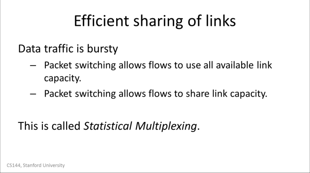
The second is that it lets a switch efficiently share a link between many parties. For example, consider a wireless router in a home with two people browsing the Internet on their laptops. If one person is reading a page, then the other person can download a file at the full speed of the link. If the first person starts loading a new web page, the link can be shared between the two of them. Once the download completes, the first person can use the full speed of the link.
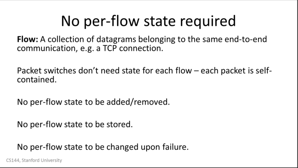
Because each packet is self-contained, a switch doesn’t need to know about groups of packets, or flows of packets. Imagine if every switch had to keep track of every single web connection passing through it. This would require a huge amount of state that would be hard to manage! Instead, treating each packet independently means the switch can be much simpler to build, manage, and troubleshoot.
The switch doesn’t need to worry about adding or removing this per-flow state. Imagine if every time you wanted to load a web page, you had to communicate with every switch along the path to set up state so your request would work. This could make things much slower. Instead, you can just send packets and the switches forward them appropriately.
The switches also don’t need to store this state. Because switches have to be fast, they’d need to store this state in very fast memory, which is expensive. This lets switches focus on doing one thing, forwarding packets quickly.
Finally,it means switches don’t have to worry about failures. Imagine, for example, what happens when you start a web request but then your tablet runs out of energy. The switch is going to keep the per-flow state for the request, but if one of the nodes that created the state fails, the switch needs to know how to clean up after it. Otherwise you can have millions, billions of dead flows eating up your memory. With packet switching, a switch has no per-endpoint state. If your tablet dies, the switch doesn’t care, it just means that it stops receiving packets from it. In this way the switch is more functionally independent of the computers sending traffic through it.
 ]]>
]]>